Working with CAD Layouts
Import CAD Files Wizard
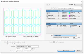 |
This dialog consists of 3 panels:
Preview Panel
The Preview panel on the left shows a preview of how the Layout Editor interprets the CAD file, with the lines and empty products shown or hidden as specified in the controls on the right.
Lines and Elements Controls
Flip CAD Layout
Select to mirror the layout horizontally or vertically.
CAD Units
Shows the measurement units as defined in the CAD file: drop-down list is disabled; if the file does not specify units, the list is enabled and you can choose a different unit than the default defined in the Apogee Preferences.
Line Mapping
A drop-down list with the CAD Line Input Maps resources available for the type of CAD file and appearing in the order as they are listed in this resource. Click the pencil icon if you want to open this resource. See “CAD Line Input Maps” for more information.
Line Mapping Table
The table lists the line types which were detected in the CAD file. They are mapped to operations according to the selected Line Input Maps resource and numbered according to their order in the resource. If a line cannot be mapped it is grayed out. All mapped lines are imported by default. Select/deselect a line in the Type (Layer) column, if you want it to include or exclude it. In the Operation column you can change the operation specified by the resource to any of the operations in the drop-down list. Remapping the operation sets the Line Mapping drop-down list to <Custom>. Lines that were not mapped automatically by the resource are set to <Unknown>.
Elements Tables
This table lists all the elements found in the CAD file, typically one or more products which are repeated in the layout and other non-repeating elements. The CAD file is analyzed during the import to recognize contour-defining lines that are mapped to stations, i.e. placeholder instances of one or more products, or background lines that may be needed for the proofing layer (indicated as *MAIN*). In the Element column, you can choose to show/hide a product or other element. The number of instances of the product or element on the sheet is also indicated. The Target column specifies how the elements will be imported:
•Stations: placeholders for empty products to which artwork can be added later; see “Mark Engraver” and “Place Station Numbers” for information on station marks.
•Proofing only: elements useful for proofing the sheet that do not represent empty products.
You can change the Target by selecting a different target in the drop-down list.
Fix
Select one of the options in the list and the CAD file will be analyzed to solve common issues in designs:
•None: Imports the CAD file as it is.
•Combined designs: Attempts to recognize individual designs.
•Nested cut lines: Attempts to reconstruct the common lines in the designs.
•Common knife lines: Attempts to recognize when the contour-defining lines are nested. The outermost lines are assumed to be the design.
For the second and third options, you can override the default maximum distance for recognizing nearby endpoints by selecting the Connect endpoints when closer than check box and entering a value higher than the default 0.8 Points.
Action and Products
Create sheet from CAD
A new sheet will be created with the sheet dimensions and arrangement of elements as specified in the CAD file.
Place Product Block on sheet
Select this option to choose your own sheet size and change the element positions. A new sheet is created. Select the sheet size from the drop-down list: current sheet size or a standard size in the list; here you can also select the size defined in the CAD file. If you want the CAD to be added to the current sheet, deselect the New Sheet check-box.
Create empty products
Select this option to create an empty product for every element that is imported as a station and to link those products to the station on the sheet.
Place Layout Button
Clicking this button will import the CAD file and place the layout on the current sheet or create a new sheet with the placed layout.
doc. version 13.1.1