Finishing Hub
 |
The Finishing Hub is where you manage cutters, finishing operations and finishing margins. You can create new resources or edit existing ones using the File and Edit menus, or by context-clicking in the various lists.
Administrator access level only!
Associated Task Processors
The Finishing Hub is available for the following Task Processors:
•Generic SD (Sign and Display Printer) and other SD printers
Open the Finishing Hub
Finishing Hub Overview
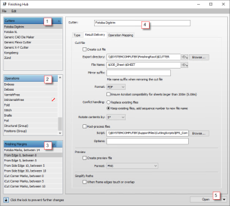 |
1 Cutters
2 Finishing operations
3 Finishing margins
4 Details of cutters, operations or margins
5 Open other resources button
Cutters
This panel lists the cutting devices. The Type and Result Delivery tabs contain the details for each cutter.
Name
The name given to the cutting device.
Type tab
The type of cutting device:
•X-Y cutter: A cutter, such as a table cutter or plotter, that can cut out any possible form and perform a variety of operations/tools.
•Roll cutter: A cutter that can cut a roll into sheets and slice them into strokes as well.
•Guillotine: A cutter that cuts in straight lines from edge to edge while taking into account the sheet layout.
•CAD Die Maker: A cutter that exports a CAD file for die-making.
Result Delivery tab
Here you can choose to create a cut file automatically for each sheet or not.
Create cut file
If the check box is selected, a cut file is generated and sent automatically to a directory as specified. If the check box is not selected, you can still send the file manually.
Export directory
The directory where the cut file is saved.
File name
The name of the cut file. The directory and file name can be generated using variables. See “System Variables” for more information on using variables.
Mirror suffix:
The suffix to append to the filename when a cut file is mirrored.
Double-sided sheets:
If the check box Create for both sides is selected, two cut files are generated, one per side. By default, check box is not selected, a cut file is generated for the front side only
Format
The file format of the cut file:
•PDF: the default and most common format for a cut file
•EPS: for large sheets
Acrobat compatibility for large sheets
Select for sheets larger than 200 inches or 5.08 m to process the file using User Units.
Conflict handling
Choose what you want to do if a cut file has the same name as an existing file: replace the existing file or keep the existing file and append a sequence number to the new file.
Rotate contents
The content of the cut file can be rotated 0°, 90°, 180° or 270° without having to rotate the sheet. The default is 0° so the cut file has the same orientation as the sheet.
Post-process files
After a cut file has been created, the system can run a script on this file, for example to change the file format:
•Script: the full path to the script you want to run. It must be accessible by the computer running Asanti. Click browse to open a file explorer and select the location of the script.
•Options: Optional arguments that can be passed to the script. They are passed as entered; the options are not enclosed in quotes or double quotes, so the script can see them as individual arguments. The file name of the cut path is always the last argument.
Preview panel
Here you can choose to create a preview of the cut file. This file is saved in the same directory and with the same file name (except the extension) as the actual cut file. The following file formats are available:
•PNG
•BMP
Simplify Paths
This section provides options to simplify the paths in the cut file.
When frame edges touch or overlap
Select this check box to simplify the paths by merging overlapping or touching lines.
NOTE: This is not only for the contour cutting operations, it simplifies the paths of any Operation.
Operation Mapping tab
This tab provides a mapping table to define whether the available finishing operations are selected for the cutter in question and how the generic names (left column) are mapped to cutter-specific names (right column).
Clear the check box next to an operation if it is not supported by the cutter.
The default operations and any operations you add in the Finishing Operation panel appear in this table with the generic name in the left column. To map an operation to a cutter-specific name, select the operation in the list and enter the cutter-specific name in the panel on the right. You can also set a Path Color for the cutting path in the cut file.
Finishing Operations
A Finishing Operation is a line that is drawn in the artwork or in a CAD file that represents various processing operations, such as:
•shape the product (e.g. Cut and Crease, Through Cut)
•identify zones that require special treatment (e.g. Gluing, Perforate)
•provide information (e.g. Dimensions).
Operation
The name of the Operation.
Special behavior
You can choose one of the following special behaviors for the selected operation, except for the Camera Registration which has a built-in behavior that cannot be changed.
•Defines product contour: A Contour-defining Operation marks the path or box that defines the shape of the final product. It is used to calculate the clipping and bleed paths, it sets the initial size of the frame and determines nesting.
•Defines ink-free zone: An Ink-free Operation provides a way to mark the ink-free areas on a product, e.g. on flaps those need to be glued together. An ink-free area only clears the content of the artwork. However, you can still have marks inside that area.
•Exclude from cut file: Operations marked with this behavior will not be included in the cut file. However, you can still proof and display them via a Line Appearances set.
•Registration: The main purpose of this behavior is to print specific CAD lines on the main output. This special behavior has no effect on how the lines appear in the client or on the proof, which is still determined by the Line Appearance sets. It has no effect on how lines are presented in cut-file, that remains controlled by the Operation Mapping of each cutter.
•None: This behavior is for backwards compatibility. Paths are made available to the cutters, but they have no other behavior.
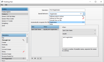 |
In the details panel, you can specify one or more conditions for applying an existing or new operation to an image automatically. The conditions can be set to check the following items in your images and map these items to a finishing operation:
•Spot color name: If you select the spot color name as condition, you can choose one of the following options for matching the value or values you enter in the comma-separated list of possible names:
•equals
•contains
•begins with
•ends with
Finishing Margins
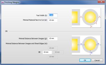 |
Finishing margins can be defined in two ways as reflected by the settings of the Finishing Margins dialog:
•Tool width (t)
•Minimum Material Next to Cut (e)
OR
•Minimum Distance between Images (g)
•Minimum Distance between Images and Sheet Edges (m)
Click the link icon if you want to set specific values for Left, Right, Top or Bottom. Margins are relative to the frame which initially corresponds with the trim box of your image.
Open Button
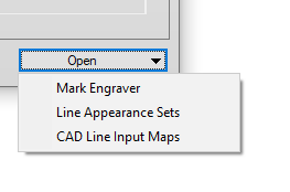 |
Click this button to open related resources:
Mark Engraver
See “Mark Engraver”.
Line Appearance Sets
The Line Appearance Sets resource is where you can control the color of the various lines that represent operations and whether or not these lines are visible on the sheet. Click a color patch if you want to change the color or thickness of the line. In this dialog you can also change the solid line to a dashed line in various styles. Click the eye icon to make the line visible or to hide it. Click the Show only visible check-box to filter the list of lines in this dialog. You can work with the default set or create your own sets that you can apply in different situations (regular proofing, imposition proof, etc.).
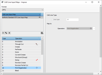
CAD Line Input Maps
This resource maps the lines detected in CAD files to operations (Cut, Crease, Perforate, Print Registration, etc.). Default maps are provided for selected CAD files formats. Select a file format (CFF2, DXF, etc.) in the Format drop-down list to see the maps for that format and then select a name in the list to see all the lines included in the map. Each line has a type number and a mapped operation that you can change in the line inspector on the right.
 |
doc. version 6.1.1