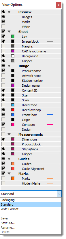
View Options Palette
The View Options palette is used to show and hide the various components on the layout. The list of available options you see in the palette depends on the layout mode you are working in – Sheet Layout or Print Layout.
NOTE: Hiding content or marks with the View Options palette does not mean they will not be printed.
The following elements can be shown/hidden:
•Preview
•Images: the content of the products placed on the sheet
•Marks: the cutting marks selected for finishing, or other marks
•White: the white layer of an image (or generated white)
•Varnish: the varnish layer of an image (or generated primer)
•Sheet
•Lay: triangle icon indicating the lay of the sheet
•Image block: the bounding box enclosing all the products
•Margins: the margin around the sheet as set in the Finishing inspector
•CAD Layout name: the name of the CAD layout file or of the Sheet layout template
•Background: the area of the sheet where no products are placed
•Ink zone: the area on the print layout where printing will effectively occur, similar to the product bleed zone (only for Print Layout mode)
•Gripper: the gripper zone of the selected Generic Press (hidden for Wide Format jobs)
•Image
•Product name: the name of the product
•Artwork name: the base name of the artwork on the currently viewed side, as shown in the Source list of the Product Editor.
•Station number: the Station number of the frame
•Design name: the name of the design as shown in the Source list of the Product Editor.
•Tile number: on a tile, the tile number, row and column numbers
•Content-ID: the content-ID of the frame, if set.
•Size: the size of the frame on the sheet as (w) x (h) (units), with units being the same units as those in the Position bar.
•Scale: the scale of the placed product, relative to its original size, as (hscale) x (vscale) %.
•Bleed zone: the bleed path the Layout Editor always draws the actual bleed content)
•Bleed overlap: the overlaps of the working bleed path
•Frame Box: the bounding box of the frame (the frame box is always shown when the frame is empty, regardless of the state of this option).
•Origin: the lower-left corner of the frame
•Contours: the contour that is used for clipping. When an image has no contour-defining Operations assigned or when its Clip to contour option is off, the contour follows the frame.
•Design: the paths and texts that associated with Operations that are present on the sheet and its products, using the appearance as defined in the Line Appearances set that is selected in the Client preferences.
•Printer (only for Print Layout mode)
•Lay: the lay of the print layout that indicates the leading edge of the layout and the home position of the printer shuttle.
•Background: representation of the surface of the printer bed or belt and more specifically the area where no printer sheets are placed
•Measurements
•Dimensions: the dimensions of the printer’s sheet or frames
•Product block: the dimensions of the product block and the distances to the sheet edges
•Steps/Gaps: the distance between the frames of two neighboring products, per pair of elements.
•Gripper: the size of the gripper (only for Offset jobs)
 |
•Guides
•Guides: the guides on the sheet.
•Guide Alignment: how closely the frames align to the guides
•Marks
•Marks: the bounding box of the marks
•Hidden Marks: marks that will not be printed due to conflicts; displayed in a red, hatched box
In the View Options drop-down list you can select, create, rename or delete preference sets for the View Options.
To show/hide content, rule-ups and marks
1 Click the Show/hide View Options button in the toolbar or choose Window > View Options to show the View Options palette.
 |
2 Click the individual or group eye icons to show or hide the various rule-ups and marks.
3 Click the colored boxes to open a color editor where you can change the color of the rule-ups and measurements.
4 Click in the drop-down list at the bottom of the View Options palette to choose, create, rename or delete preference sets for the View Options.
doc. version 6.1.1