X-Rite
eXact Scan
NOTE: QMS only supports the X-Rite eXact when equipped with the scan option.
Install the most recent device driver available from the application CD (X-Rite_eXact_driver_v3.02.exe or later from the driver folder) or use the Apogee Client installer as described on “To install a Measurement Device:”.
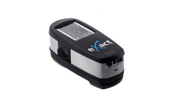 |
To measure a Target:
1 The X-Rite eXact can be connected either with a USB cable or with a Bluetooth network connection. Make sure the eXact is paired with the Windows Bluetooth module on the Windows system in order to establish a Bluetooth connection.
When connecting to the eXact for the first time, a pairing code must be entered. This code is “Default” and applies to all eXact devices. If you are having trouble connecting via Bluetooth, consult the user manual (found on the CD) or use the Apogee Client installer as described on “To install a Measurement Device:”.
The settings dialog is used to manage the QMS Measure connection once it has been paired.
2 Measuring can only be done with an ID strip. Measure the ID strip in the indicated direction (left to right). It is possible to measure the strips in either direction.
To start measuring, position the target window aperture over the first patch of the color bar, lower the instrument, hold it steady until the speed indicator appears on the display or the instrument beeps, then roll the instrument continuously over the color bar, and stop on top of the last patch.
The Measuring Modes M0, M1, and M2 are supported when using X-Rite eXact, although the device also supports M3 the ECO3 (AGFA) measurement interface does not support it.
The Measuring in M1 mode only requires one scan.
NOTE: The measurement head's little lever must be switched between positions I and 0 to go from M1 to M0. Position I is used for M1 mode measurements, and position 0 is chosen for M0 or M2 measurements.
3 The eXact controls its calibration process; before the calibration procedure is initiated, it will ask to be placed in a stable position; otherwise, it should be left untouched.
4 It is also possible to measure without an ID strip. In this case, use a color bar on the right side without any additional color encoding patches, or measure from right to left beginning with the patch that comes before the last patch (i.e., excluding the color encoding patches).
eXact 2
The eXact 2 is a “look through” device. This device uses a camera system for manual positioning. The eXact 2 can connect via Wi-Fi or USB. There is no Bluetooth interface. The measuring of wedges is based on an ID strip.
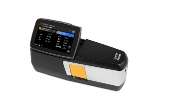 |
To measure a Target:
1 The X-Rite eXact 2 can only be connected with a USB(C) interface. Connect the eXact2 to your PC before launching the measurements.
2 Measuring can only be done with an ID strip. Measure the ID strip in the indicated direction (left to right). It is possible to measure the strips in either direction.
There are four Measurement conditions M0, M1(D50), M2 (UV exclude), M3 (Pol filter), and two methods: Scan or Spot.
There are two orange buttons on the device: the larger one is the brake button, located on the left side of the body. It can be locked in the un-braked position by sliding the black slider underneath it to the right.
The Measure button is on the right side of the body; press and hold it while scanning.
The eXact2 display indicates the measurement head's position (white circle) as well as the guides that need to line up with the colorbar.
3 Start measuring on the first patch, move the device in line with the colorbar without pausing and stop at the last patch or just next to the last patch of the colorbar.
X-Rite i1
The X-Rite i1 drivers, including the handheld and iO table are not compatible with all generations of measurement devices. For this reason, it is important to select the right driver for the right device.
X-Rite i1 Measurement Devices | |
|---|---|
i1 (before 2010) Driver: i1 (IO) | 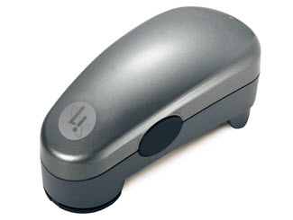 |
i1 Pro II (from 2010) Driver: i1 (IO) 2 | 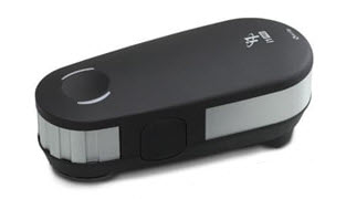 |
i1 Pro III (from 2019 and later)) Driver: i1 (IO) 3 | 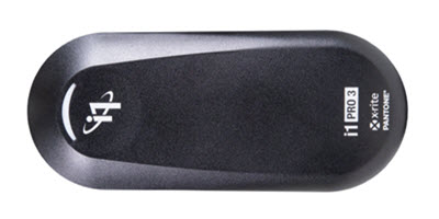 |
i1 Pro III Plus (from 2019 and later)) Driver: i1 (IO) 3 Plus | 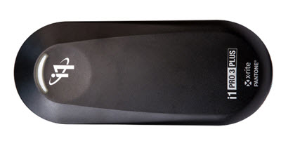 |
X-Rite i1 Pro 2
To measure a Target:
1 Select new Automatic Measurement from either the file menu or using the + icon in the measurement pane. A Measure wizard window will open.
2 Select the measurement device, target, ID strip, measurement settings (like the number of measurements, etc.), Measurement mode (M0, M1 or M2), calibrate the spectrophotometer and initiate the measurement. Once all the parameters are set up, the Measurement progress view will be shown.
3 Depending on the measurement device type, the measurement data will be filled in row by row or page per page. Green buttons mean enough measurements for the row/page are done, and red indicates that the row still needs to be measured.
4 M1 Scan measurements require two measurements per row, one from left to right and one from right to left. The indicator lights on the device will turn blue to indicate the measurement direction. Right LED means measure from left to right, left LED means measure from right to left.
X-Rite i1 Pro 3 and i1 Pro 3 Plus
The i1 Pro 3 is used in a very similar manner to the i1 Pro 2 with the exception of measuring with M1, which only requires measurement in one direction.
It is possible to measure in both directions.
The i1 Pro3 Plus and standard i1 Pro 3 differ only in that the Plus model's aperture measures 8 mm, while the standard version measures 4.5 mm. This has an impact on the patch sizes that are supported, the standard version can handle patch sizes ranging from 8x10 mm to 15x15 mm, while the plus version requires 16 x 16 mm.
The 591 mm ruler that comes with the i1 Pro3 Plus model enables scanning of charts that are 515 mm wide. This version has a larger backup board (670x452 mm vs. 355x400 mm).
X-Rite i1 iO
The i1 iO table is a robot arm that can carry an X-Rite i1, i1 Pro 2 and i1 Pro 3 (Plus) allowing to scan charts in an automated way. There is a dedicated version of the iO table for each i1 generation. They are not exchangeable.
The I1 iO needs a slightly different positioning of the sheet, when M1 is enabled. Due to the specific M1 routines, an imaginary extra spot of white needs to be foreseen at the beginning of each line. This means that the best positioning of the sheet is in the lower right corner.
NOTE: The i1 IO Pro 3 can be combined with the i1 Pro 3 Plus, but needs specific glider rings with a larger hole.
X-Rite i1 iSis
The X-Rite i1 iSis is a scanning device that is capable to measure targets printed on thinner paper and available in two sizes; Standard and XL. QMS supports two generations:
•X-Rite i1 iSis: M0 and M2 (UV-cut) measurements (discontinued)
•X-Rite i1 iSis 2: M0, M1, M2 measurements.
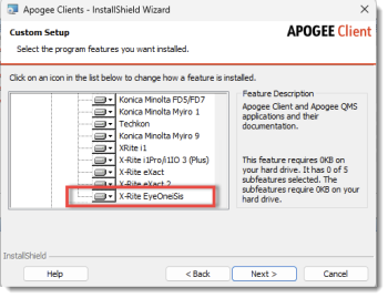
NOTE: The iSis and iSis 2 do not have their own drivers. In the Client Installer, the driver is listed as X-Rite EyeOneiSis.
 |
To measure a Target:
1 Connect the i1 iSis with a USB cable to your computer. Verify that the Windows operating system can recognize the device.
2 Click the Measure icon to initiate a measurement.
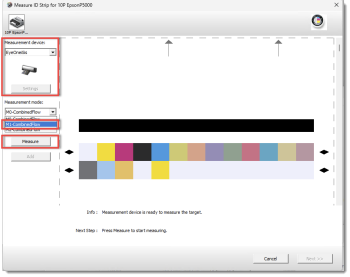
3 Select the iSis from the Measurement device drop-down list. QMS will recognize the measurement mode capabilities from the device.
Select M1-CombinedFlow, and click the Measure button to start the measurement.
 |
4 The device will initialize. Wait until the indicator flashes green. Align the wedge to the left edge and gently feed the wedge in the device. Release the wedge when the device picks up the chart.
5 QMS will proceed to the main measurement once the ID strip is recognized.
6 Repeat the procedure for all wedges of the job. Click Add, if there are multiple measurements, and click Next to accept the measurements.
doc. version 13.1.3