Measuring the Profile Target
Proceed as follows when measuring the Profile Target:
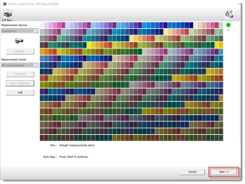
1 Click the Measurement button in the Quality Management window.
2 Measure the target in accordance with the connected measurement device:
•Measure the ID strip
•Select the measurement description file or the measurement file (in case of the SpectroProofer).
3 Change the measurement parameters (like measurement mode, scanning, etc.), if needed.
4 After the measuring is completed, and the system has enough information, the Next button becomes available.
 |
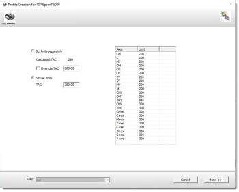
5 Click the Next button. The ink-limited target values are shown including almost all possible; two, three, and more ink overprints that go up to the maximum.
Use this ink-limited target if drying problems are observed. These problems point to a problematic ink limitation when combined with the loaded paper.
NOTE: The ink-limited target is not needed for the ECO3 branded substrates (all quality resources are optimized for these papers).
6 Keep the ink limitations at their maximum and click the Next button.
 |
7 QMS will continue on to the instructions for creating a profile.
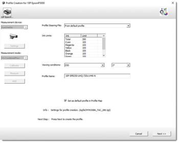 |
Apogee selects the Profile Steering file. Use this preselected profile steering file (From default profile).
NOTE: It is not recommended to use other targets since these specific targets can be developed for outdated technology (CMYK6_all) or other printing techniques (lithography, industrial inkjet, etc.).
8 Adapt the ink limits, if necessary.
NOTE: Patches that are prone to inversion are excluded from targets that are designed with TAC (Total Area Coverage) or ink-limiting in mind. As a result, there will be no inverted data in the measurement file that is obtained from these targets. This eliminates the need to later remove any zones from the profile in order to prevent inversions and enables the creation of a profile based on the entire set of measurements. On the other hand, if inversions are still visible on the target, a new target with a lower ink limit needs to be printed. These ink-limited goals are designed to comply with the particular ink limitation configurations that were set during the ink limits procedure.
9 The viewing conditions are needed to match the viewing conditions of the press profile. A mismatch of these settings will cause bad color reproduction. (D50, 2 degrees observer).
Using the AdvancedCMM functionality, Apogee Prepress can convert between profiles with various viewing conditions. The calculation between profiles under varying viewing conditions will require a little more CPU time.
10 Enter a Profile Name for the proofer profile.
11 Enable the option Set as default profile in Profile Map to automatically select the profile, when a job uses the same quality and ink table. See “Adding a Proofer Profile to Profile Selection Map”.
12 Click the Next button.
13 The Proofer Profile is created. An overview of the parameters entered will appear. Click the Save button to add the profile server’s Proofer Profiles.
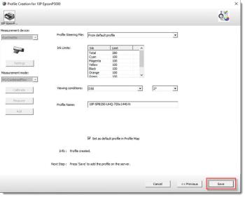 |
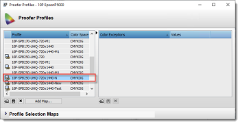
14 The Proofer Profile is added to the server. Proofer profiles can then be managed via the Apogee Prepress Client’s System Overview window.
 |
 |
doc. version 14.0.1