Tiling Inspector
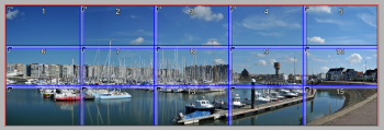
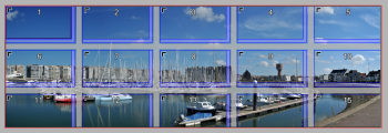
Use the Tiling inspector to divide a master image into parts, i.e. tiles, that can be printed independently of each other. After applying tiling, the tiles appear in the Product panel of the Layout Editor as individual images which can be placed on sheets for printing. The printed tiles are subsequently mounted to recreate the original master image.
The master image may have canvas extensions, and tiling is then applied to the total image area that consists of the image and the flaps.
Overlaps and non-content gaps
In most cases, the individual tiles will need to have overlaps on one or more sides so they can be assembled on top of each other – for example, the various panels of a billboard. These overlaps are added to the visible size of the tiles. The total size of a tile is the visible size plus the overlap and bleed. However, in some cases, overlapping is not necessary or possible – for example if thicker materials are used. Other applications may require that gaps are created in the content between the tiles.
 |
Tiling check box
Selecting the tiling check box enables the tiling settings in the inspector where you can set the parameters to let the system create tiles automatically. The check box is also selected and the inspector activated if you are creating your tiles manually. See “Interactive Tiling”.
NOTE: Clearing the Tiling check box will delete all interactive tiling actions you performed on the image.
Tiling menu
Click the cogwheel to reveal a menu with the following commands:
Re-apply tiling set-up
Resets the tiling arrangement according to the settings in the tiling inspector, undoing any interactive tiling actions.
Preferences
Opens the Tiling Preferences dialog box with the settings for creating the montage instructions. See “Tiling Preferences”.
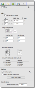 |
Tiles
At the top of the Tiles panel you can specify how you want to create your tiles: the number of columns and rows and whether you want the tiles to have the same visible size or the same total size. Alternatively, you can specify the desired dimensions for the tiles – again based on either the visible or total size – and the system will use these dimensions to split the image. In this case, the last row and column will probably have tiles with different sizes to accommodate the remaining content of the image.
Tile for current media
Select this check box to let the system tile your image so it fits on the sheet or roll media currently being used. For example, a large image can be split into 3 tiles so it can be printed on the media. Selecting this option clears any manual settings you made.
Nr
To start tiling, enter the number of columns in the box with the horizontal arrow and the number of rows in the box with the vertical arrow.
Total Size/Visible Size
You can choose the total or visible size by clicking the black triangles to display the drop-down list:
•Visible size: the area of the tile that will be visible after mounting
•Total size: the visible size plus overlaps
Last
The width of the last column and the height of the last row; only filled if you specify a desired size for the tiles.
Tiling arrangement
A tiling arrangement can be chosen depending on whether you need overlapping tiles, non-image gaps between tiles, or extensions to recreate the master image from the tiles:
Overlaps
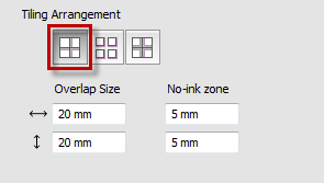 |
Select the Overlaps arrangement if you need overlapping tiles. Enter a horizontal and vertical size for the overlaps. The overlaps are areas with duplicate image content so the tiles can be mounted on top of each other. Enter a non-ink zone if you want part of the overlap to remain blank so the overlapping materials adhere better to each other.
 |
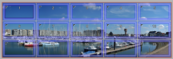
Gaps
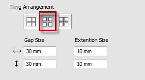 |
Select the Gaps arrangement if you need content gaps between the tiles. The content gaps are not printed. Self-adhesive tiles for window panes are a typical application of gaps. Enter the gap size, for example the width of your window frame, and half of this size is deducted from adjacent tile edges to create the full gap. Enter extension sizes to create extra material with content to cater for size variations. Extensions are added to the sides opposite to the tile anchor, except along the outer edges of the image.
 |
Symmetrical
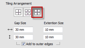 |
Similar to the Gaps arrangement but with extensions on all sides. Select the Add to outer edges check box to add extensions to the tiles along the outer edges of the image.
 |
Montage Sequence
Here you specify the order for mounting the printed tiles, how the tiles are numbered, and on which edges the overlaps or gaps are located. This is done by combining the First Tile and Proceed buttons that provide a total of 16 combinations.
First Tile
Select the corner where you want to start the numbering of the tiles: top left, top right, bottom left, and bottom right. The sequence numbering starts with the tile that is to be mounted first and the anchor symbol moves to the respective corner of each tile. The tile overlaps, gaps or extensions are created accordingly.
Proceed
The logic of the sequence numbering is controlled by four buttons in the drop-down list. These let you choose the horizontal and vertical direction in the grid. The default sequence is with the first tile in the top left corner. The numbering then proceeds horizontally along the first row (left to right) and then on the following row in the same direction (left to right). Depending on the selected first tile, the following combinations are possible:
 |
NOTE: The drop-down list only shows the four sequences that are possible with the selected first tile.
Actual Total Sizes (including bleed)
The Smallest and Largest total tile widths (horizontal arrow) and tile heights (vertical arrow) – not necessarily the same two tiles.
Various
Print tile marks
Prints tile-specific marks on the tiles. See “Tile Marks Dialog”.
Export montage instructions
Select the check box if you want the system to automatically create a PDF document with instructions for mounting the tiles when you submit the job. Click the Export and Open button without or with the check box selected to see the PDF with instructions immediately. See “Montage Instructions”.
Constraints
Minimum Visible Size
Defines the minimum visible tile size.
NOTE: The minimum visible tile size must be at least 5 mm.
doc. version 6.1.1